Network Layer
The third layer of the OSI Reference Model is the network layer. The network layer provides quite a few functions. First, it provides for a logical topology of your network using logical, or layer-3, addresses. These addresses are used to group machines together. The network component is used to group devices together. Layer-3 addresses allow devices that are on the same or different media types to communicate with each other. Media types define types of connections, such as Ethernet, Token Ring, or serial.
To move information between devices that have different network numbers, a router is used. Routers use information in the logical address to make intelligent decisions about how to
reach a destination.
Examples of network layer protocols include AppleTalk, DECnet, IPX, TCP/IP (or IP, for short), Vines, and XNS.
Data Link Layer
The second layer in the OSI Reference Model is the data link layer. Whereas the network layer provides for logical addresses for devices, the data link layer provides for physical, or hardware, addresses. These hardware addresses are commonly called Media Access Control (MAC) addresses. The data link layer also defines how a networking device accesses the media that it is connected as well as defining the media’s frame type.
This includes the fields and components of the data link layer, or layer-2, frame. This communication is only for devices on the same data link layer media type (or same piece of wire). To traverse media types, Ethernet to Token Ring, for instance, typically a router is used.
The data link layer is also responsible for taking bits (binary 1’s and 0’s) from the physical layer and reassembling them into the original data link layer frame. The data link layer does error detection and will discard bad frames. It typically does not perform error correction, as TCP/IP’s TCP protocol does; however, some data link layer protocols do support error correction functions.
Examples of data link layer protocols and standards for local area network (LAN) connections include IEEE’s 802.2, 802.3, and 802.5; Ethernet II; and ANSI’s FDDI. Examples of WAN connections include ATM, Frame Relay, HDLC (High-Level Data Link Control), PPP (Point-to-Point Protocol), SDLC (Synchronous Data Link Control), SLIP (Serial Line Internet Protocol), and X.25. Bridges, switches, and network interface controllers or cards (NICs) are the primary networking devices functioning at the data link layer.
Physical Layer
The first, or bottommost, layer of the OSI Reference Model is the physical layer. The physical layer is responsible for the physical mechanics of a network connection, which include the following:
■ The type of interface used on the networking device
■ The type of cable used for connecting devices
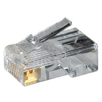
■ The connectors used on each end of the cable
■ The pin-outs used for each of the connections on the cable
The type of interface is commonly called a NIC. A NIC can be a physical card that you put into a computer, like a 10BaseT Ethernet card, or a fixed interface on a switch, like a 100BaseTX port on a Cisco Catalyst 1900 series switch.
The physical layer is also responsible for how binary information is converted to a physical layer signal. For example, if the cable uses copper as a transport medium, the physical layer defines how binary 1’s and 0’s are converted into an electrical signal by using different voltage levels. If the cable uses fiber, the physical layer defines how 1’s and 0’s are represented using an LED or laser with different light frequencies.
Data communications equipment (DCE) terminates a physical WAN connection and provides clocking and synchronization of a connection between two locations and connects to a DTE. The DCE category includes equipment such as CSU/DSUs, NT1s, and modems. Data terminal equipment (DTE) is an end-user device, such as a router or a PC, that connects to the WAN via the DCE device. In some cases, the function of the DCE may be built into the DTE’s physical interface. For instance, certain Cisco routers can be purchased with built-in NT1s or CSU/DSUs in theirWAN interfaces.
Normally, the terms DTE and DCE are used to describe WAN components, but they are sometimes used to describe LAN connections. For instance, in a LAN connection, a PC, file server, or router is sometimes referred to as a DTE, and a switch or bridge as a DCE.
Examples of physical layer standards include the following cable types: Category-3, -5, and -5E; EIA/TIA-232, -449, and -530; multimode and single-mode fiber (MMF and SMF); Type-1; and others. Interface connectors include the following: AUI, BNC, DB-9, DB-25, DB-60, RJ-11, RJ-45, and others. A hub and a repeater are examples of devices that function at the physical layer.


No comments:
Post a Comment